Industrial Zone
Using the previous
steel structure procedures and some new bits and pieces I've been building a
few elements for populating the industrial areas of the city. For now we have:
- Warehouse or factory building, with roof-top windows/solar panels, and chimneys.
- Round storage silo or tank, with and without steel support structure around it.
- Simple tower based on the steel-work structures.
- Simple chimney of a couple of different styles.
During the creation
of these, I've been regularly checking the look of the city. I was pleased with the initial appearance and
the variety and layout was working well giving a good view.
A Recurring Problem
As more elements and
more detail were added, holes in the industrial blocks often appeared.
This is an indicator
of a procedure synthesis running out of buffer space, due to either too much
geometry (triangles/lines) or too much calculation (procedure
depth/complexity). To find the problem
procedure a bit of digging using the view diagnostics panel is required thus:
- Set render depth to show only the tier with the problem in.
- Turn on octree node display.
- Set octree node depth to match render depth selected above.
- Set the node highlight to the node surrounding the problem area.
This should show up
the actual error message (stat shows first error message under node). To see exactly what happened during the
synthesis of this model we can perform these further steps:
- Open the engine dev panel to show the synthesis monitoring panel.
- Switch on node model filtering to only render models under this node.
- Set the model select to only render the problem model.
- Request synth analysis graph generation (triggers re-synth).
 |
| Second stage of diagnosis; which exact model? |
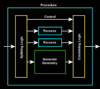
From this we can see
that we are running out of parameter buffer (abbreviated to 'Control' here), the memory used for all the
information flowing between and through the procedures as the calculations are
performed. This will be because the city block sub-division is quite demanding due to there being
quite a depth to the process between the top level of the city at which we are
starting and where we actually start to generate geometry.
Turning Up The Heat
Hitting these
problems has left me feeling a bit in the dark about how well the system is
performing in general, how close we are to having them happen again else-where,
and where else we may need to improve the procedures building our scene. It is a balancing act fitting the design and
requirements into the resources available (as is often the case), but this is
going to be a common workflow occurrence and we need more tools to help us
monitor the situation as we work.
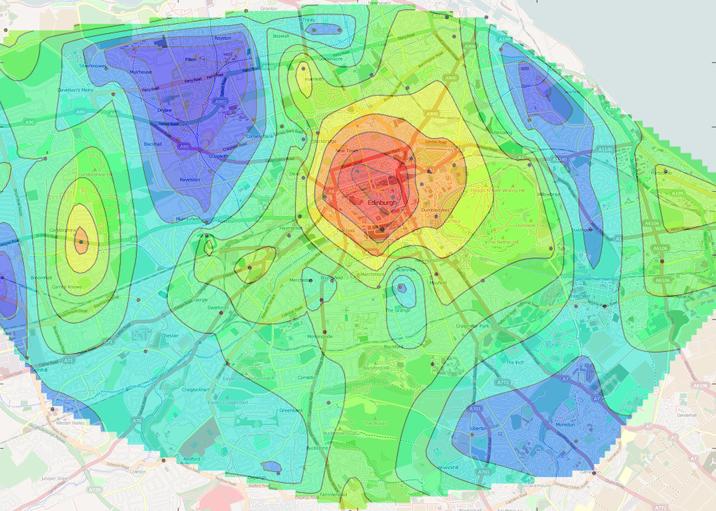
A visualisation tool often used for
assessing the overall level of something and getting a good feel of how some
value varies across a space is a heat-map.
There are many
metrics we could benefit from being able to visualise such as:
 |
| An example of a heat-map |
- Rendering cost (triangle count, draw calls, materials)
- Memory use (system memory, GPU memory, synthesis buffer)
- Synthesis cost (time/cycles taken, buffer use)
- Measures of complexity (synth depth, stack use, passes generated, analysis, refinement level)
- Scene complexity (octree nodes, model counts, mesh counts, node status)
All of these help us
assess the overall cost and effectiveness of the procedures creating our world.
Some support work
was required to capture the statistics needed from the synthesis process, and
propagate it through to the rendering stage (with the meshes). Plus, because
the output of synthesis is often merged into single meshes, we also needed a
way to render parts of meshes separately to give per-procedure colourising.
Each new display
mode has its own scale configuration setting so that the range of values being
visualised in the scene can be seen in the most detail by spreading them across
the full colour gradient.
By also having
a distinct colour for a 'maxed-out' value, i.e. on or above the scale setting
we can interactively measure the value on a particular element in the scene by
dialling the value up and down until we are on the changeover point between
being the top end of the gradient and the highlight colour.
 |
| Gradient scaling settings for each heat-map mode |
I'm not 100% happy
with the choice of colour gradient, but full spectrum gradients (which I
assumed would be best) seem more suited to continuous functions and not the
more random patterns we get here.
Instead I'm trying a simpler black-blue-cyan-white 'icy' gradient, with
red for out-of-range values (above the chosen scale setting).
Hot In The City
Testing these
display modes out on Future City as a whole shows that we are actually in a
pretty good position with fairly low quantities of geometry and no hot-spots
that really stand out as problematic.
It looks like we can
actually afford a fair bit more geometry and detail, but at the moment we can't
afford synthesis cost (hence the holes).
In the upper (distant) tiers most models are in
5,000 to 10,000 triangle range, and the lower tiers are at about 1,500 to 3,000 triangle range, which is pretty low for assets these
days, with the overall GPU memory at about 100MB with the viewpoint in
the centre of the city. The draw-calls
are moderately high at about 1,000 but this shouldn't change much as
more detail is added and can be improved in other ways later on (I'm not doing
a frustum cull yet for example!).
So, we need to
reduce the synthesis cost. There are a
couple of ways we could go here:
- Reduce the complexity of some of the more complex procedures, for example we could convert our super-splitter procedure (see last weeks post [link]) into an operator.
- We can re-balance the way each synthesiser's buffer is allocated so there is more parameter space available (and less geometry space).
- We can look at one of the several planned optimisation passes on the synthesis processing and evaluation itself.
- Other ways? (there are always other ways).
At the moment I
think it is a bit premature to bake the Splitter proc into a procedure as we
lose the ability to live edit and continue to improve it (much slower
turnaround). Some investigation of the
usage of buffer memory would be helpful in deciding on a new parameter/geometry
split for the buffers, perhaps with a buffer use heat-map mode? I didn't want to get into optimising the
synth system yet as I think I can get more elsewhere first and it's tricky
work.
Hot-line
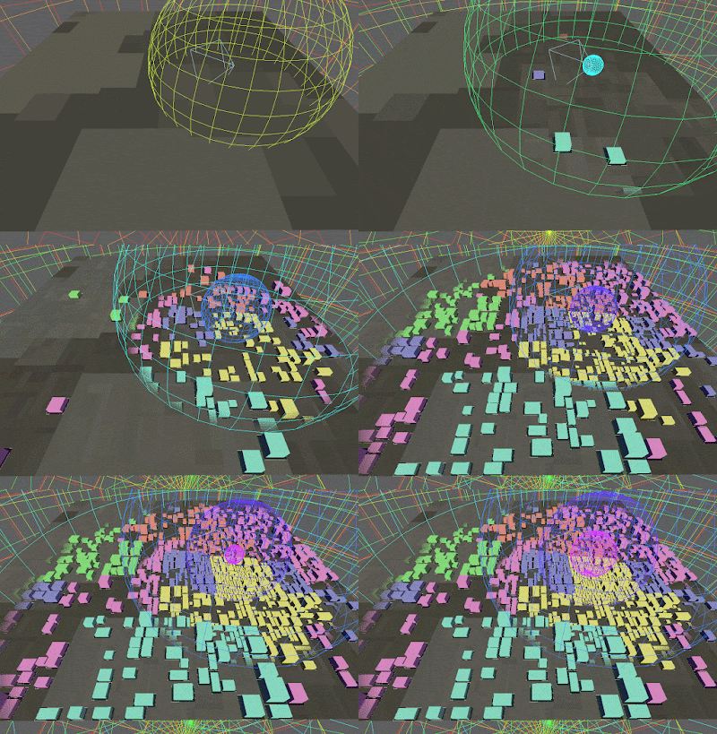
I did do some work
simplifying the steel tower procedure, which seemed particularly bad, using
line primitives (which I have so-far not needed). In the far distance, the steel beams reduce
down to 8 triangles each, but this seemed too much so I added an extra detail
switch to a single line segment. This
helped the geometric/visual detail level, but didn't help the synthesis complexity as we were
still having to sub-divide down a lot to get to the individual girders. Instead of relying on these line based beams
I remembered I had a line grid primitive (originally used to draw the
ground-plane grid) and so switched this in at a higher level for the steel-work
side sections. Thus each tower is now
made of four grid primitives in the distance.
I took this a stage further by double the grid cell size progressively
too as I noticed that the fixed width (screen space) line rendering becomes a
solid block when the tower is really small.
This helps keep it looking thinned out and again reduces the render
cost.
 |
| Reduction in tower complexity at lower detail levels by use of line (grid) primitive. |
Late Night Ideas
One night last week
I couldn't sleep for thinking about these problems and an enticing thought
occurred to me about how I can neatly improve this synthesis depth/complexity
problem by an order of magnitude and allow lots more detail for the distant
city. This will help a lot for aerial
views of the city where you should be able to see a huge amount of small detail
when at a considerable distance (probably the worst case scenario). I think I'm going to explore this next after playing with the synthesis memory balancing. More
details next time… maybe…


