Showing posts with label detail. Show all posts

Tuesday, 13 December 2016

Future City: Update 10 - Progress Gallery

Not many words today, just a quick rundown of the new and improved aspects of the city.

Aerospace

A quick space-port/airport cobbled together from other city parts to just get rid of the last placeholder zones.
First pass aerospace district, the black will be landing areas for ships.

Parks

Time for some low level detailing, quickly knocked up and assembled a variety of simple small-scale park features; benches, bins, flowerbeds, huts, and a stepped plinth.  I even added a simple tree model that can be refined later.
Parks and recreation, now with 'furniture'
More green space in our cities

City Green Spaces

Plugging the park 'furniture' into the business district open spaces instantly improved the sense of scale.
Business district park areas, a nice spot for lunch
Adding a sense of scale to the large skyscrapers

Residential

My multi-celled apartment complexes and various street/terrace configurations lends to a nice residential area feel.
Residential areas, lots of apartments, terraces, and streets
Example street layout, with variable back-yard spaces

Detail Boost

Some time spent tweaking parameters and diagnosing detail problems has seen a nice boost in detail levels, meaning we can start to see the promise of the system even more.
Overview of various city zone types, now in even more detail
10 kilometres of city in view from on high

Next

Now I'm finally going to get on to height variation and simple terrain modelling for the surroundings and green areas of the city…

Monday, 24 October 2016

Future City: Update 8 - A Mixed Bag

I haven't managed to write anything this last week (or two) due to other things going on in my life (shock!), and not really feeling like I've been focused on one particular thing.  Instead of a themed post let's just have a look through what's been going on.

Refinement Fixes

Spent some time tidying up the city a bit.  There are a few places where detail refinement was being blocked so I investigated those.
  • Empty Stacker recursion procedure leaf nodes were not ignored.
Stacker Merge appears as leaf when no further content needed, but should be ignored as not a geometry producer itself.
(excuse low-res image, Cairo scaled it down because the GraphViz output was too large)
  • Temporary general triangle fill added for rooftops didn't support refinement.
Roof triangle refinement - before and after
  • Bolts had bounds that were too large, needed to be pre-shrunk.
Bolt bounds blocking refinement - additional re-size in procedure to fix
  • Mesh primitive operators were not being counted as geometry producing (which broke the fix for the Stacker recursion issue above).
Post load checks to classify operators by whether they modify/produce geometry or not.
  • Unnecessary deep refinement of surfaces meant a deluge of synthesis when you strayed very close to a surface. This was slowing things down a little so I added a limit check in the sub-division process.
Adding a refinement limit test, whilst also abstracting out the recursion check to make it more re-usable.
To help track down some of these I added a bit more error diagnostics information:
  • Capture errors show in view panel for selected node
  • Error filter slider for when too many to display at once
  • Any bounds information in the error messages is visualised in red
Additional error diagnostics - better messages, error select, and bounds rendering

More Girders

Couldn't resist more girder improvements as this has become a bit of an 'extreme detail' test case.
  • Washers under nuts
  • Proper facets on bolts
  • Threads on the bolts (hacky, but fine for now)
Washers, faceted nuts, and threads.
  • Added cross bracing to girders
  • Fillet pieces for cross bracing
Cross-bracing and attachment fillets
  • Added rolling fillets to I-beam section
  • Added welds to fillets and fixing plates
Welds and I-beam section forming fillets
All a bit excessive, but some good tests of the detail management refinement systems.  Several issues and bugs were surfaced from this work.

The Wilderness

To make the city more interesting, and provide more of a 'setting' for it I decided to surround it with a Rural district type.  Currently just green/grass, this breaks up the city tone and gives it a rounder appearance.
Rural district type now surrounds the city.
This will provide something to have as the backdrop, or vista, when height support is added and we can have hills and mountains in the background.
This was implemented by re-purposing the commercial district type and giving it a negative gradient along it's radius instead of a positive one like the central districts.  I also parameterised the location, sizes and weights of the district types so we get much greater city layout variance as we vary the city seed values.
Some parameterised city examples

Demo Planning

I'm aiming to have my first-pass city demo-able by the end of the year, and so far I feel like I'm on track for that.  I thought I'd better make a clearer plan though so I spent a morning breaking down the things I have left to do and thinking about the timings.  Here's the to-do list:
  • Finish filling out the placeholder zones (1) - I really need to fill in the residential and leisure areas as they will lend a 'more human' aspect to the city (business and industrial so far).  I'm postponing commercial and spaceport as there are more important things to focus on.
  • Implement first-pass landscape support (1) - A big thing this city doesn't have yet is elevation.  It was always something I wanted to do to add richness and interest to the city.  So we need support for a height function (of some sort), blending (to interface with flat parts), and placing of blocks on landscape (giving them the appropriate elevation).
  • Height integration (1) - Once supported, the natural areas (leisure, surround, and business in-fill) and the interfaces between adjacent elevations need content to provide pleasant and realistic transitions.  This will need to take into account block boundaries, height, and importantly; access ways (or lack thereof) between blocks.
  • Detail pass (2) - Another pass is needed to add more detail to the low-level city, that you will see when 'walking around' at street-level. This includes features like doors, windows, pavement, as well as assets such as bins, streetlights, benches, planters, and maybe trees.
  • Navigation/viewing (1) - To demo this city properly I need people to be able to control the camera in the standalone player.  This would start with basic is keyboard/mouse (FPS) support, with controller support coming later, and then maybe an attract-mode camera mode if there is time.  This would be quite involved as it will need to 'explore' the city to find good camera positions and paths (for some definition of 'good').
  • Lighting (4) - I'd really like to try out my lighting ideas, they should really bring the city alive.  This would also include some fogging/haze/sky work, and maybe some simple clouds for fun.
  • Bonus: Transparency and reflection - If I get time or want a break for something more adventurous I'll try and get some transparency and reflection support in to allow water and glass effects to be added.
Timings (in brackets) are estimated weeks.  We'll see how it goes as I am already a little behind and am still due to have some time off.

Next

I need to get the residential parts populated as soon as I can, so I'll be looking at more 'house-like' buildings and how to create them.

Monday, 12 September 2016

Future City: Update 4 - Down To Business

This week I've been developing the business district layout a bit, dealing with a few bugs, experimenting with gradients, optimising the rendering, and adding a few features and fixes to help diagnose problems.  Oh, and it was my birthday too :)

Business

The business district is going to be lots of tall, close-packed skyscrapers with occasional open spaces amongst them.  With the area we are covering there are going to be a lot of buildings, and a lot of geometry.  To deal with this we have to introduce the buildings (and gradually higher detailed versions of them) progressively as we get closer.  Since a 'Manhattan skyline' area of a city tends to be visible from a long way off we are going to have to introduce buildings from quite a distance away.  We can do this gradually, and as long as there are some of the tallest ones appearing early on we should get a good impression of a distant city.
Distant 'Manhattan skyline' effect from larger buildings
At the moment we will just use a simple boxy model for the buildings, which should suffice for distant buildings, but will need to be replaced for the closer ones.  The detail testing/switching logic for the skyscraper uses the building height to judge which detail band they should go in.  I set it up to introduce the tallest ones in a large/distant range, the mid-height ones in the next one and the smallest ones in the closer range.  The small ones can be left until quite close before we even fade them in.  Once the viewpoint is within the city, most of what you should be able to see has been faded in.
Inner city, all building proxies faded in.
Most business district blocks are of a size suitable to house a single building.  If they are a bit long or large still we sub-divide a little more and instantiate a couple of similar buildings.
At the moment we will ignore the connectivity and access situation at the periphery of each block that we saw set up in previous posts.  It's not that we aren't going to use this information eventually, but barriers and division are probably not a big features in a business area.  To postpone this for now I added a periphery clearance space around the edge of each block.  This can be later be filled with open-space furniture (benches, water features, trees, etc).  These will carry the open space blocks in the city in amongst the buildings too.
Clearance around buildings connects with open areas.

Detail Comparison

It proved quite tricky to get my head around how to get the building reveal/distance calculations to work in such a way that it was clear what the effects of the control parameters were.  Sometimes it's very easy to set something up like this and then just 'give up' by randomly fiddling with values until it seems to be working well enough.  The first attempt was like this; the values were too arbitrary and I wasn't sure what effect they were actually having.  By stepping back, thinking about the problem in a slightly different way I ended up with a system that works.  The problem was that we have two values with different meanings to compare; the height of the building and the size of the block they are being instantiated into.  Instead of trying to massage one into the 'space' of the other it is easier to convert both into an intermediate, neutral range.  Turning both into a normalised 0 to 1 range and then comparing them seems easier to calculate and balance.
When should we introduce a distance building?
Since the block size are powers of two, it also seemed a good idea to changing them to a linear value for the purposes of comparison too.  This produced the following stages of building reveal.
Stages of distance skyscraper population, far to near.

Gradient Surfaces

Using a simple box for each building quickly blocked refinement as a geometry from a normal box primitive can't be sub-divided automatically.  This has been fixed before by using the generic rectangular patch procedure (see previous post) which sub-divides and adds some interesting extra surface detail.  Since this is a bit 'blocky' I decided to try to implement a smoother version.
Block vs. Smooth surface patch procedure
Until now, all modelling primitives have only supported painting in a single flat colour (all models use vertex colour to drive their diffuse appearance), so to introduce smoother, gradient based surfaces we need another primitive or paint operator.  I decided that a flat rectangular sheet primitive with corner colour inputs would serve best to keep the amount of pre-processing and complex painting around it in the procedure to a minimum.
Coloured Sheet primitive for creating smooth gradient surfaces
Similar to the generic patch, we will be introducing variations in the colouring as the sub-division happens to add detail.  This time however, it's a bit more complicated as the adjacent pieces need to share colours along their boundaries.  Also, we aren't going to vary a single colour, we are going to blend between two main colours as this helps keep the colours consistent as we divide deeper.  By carrying both a blend factor and a seed value with each corner vertex down through the sub-division process we can ensure that as each edge is divided up and perturbed by the same amount from each side.  We end up with a variation on the mid-point noise algorithm and build up a nice surface detail as we get close.
Increasing sub-divisions of smooth patch procedure (high contrast detail setting)
This provides us with a couple of nice features when applied to the buildings:
  • More interesting surfaces (not just flat).
  • Fewer edges visible, less blocky
  • Even the lowest detail buildings have gentle gradients across them.
Smooth patch applied to low-detail skyscrapers in business district.

Summary

This gives us low-ish detail city buildings, which we will re-visit in the future to fully detail and flesh out.  For now though we are going to look at other district types and get them up to a similar level of detail.
This example demonstrates a couple of significant advantage of the procedural approach to modelling:
  1. Re-visiting models to add detail later is a normal part of the process.
  2. Upgrading fundamental elements used across your environment will automatically be applied everywhere it is used.
  3. Building up your scene breadth first instead of having to work depth first means your scene builds up as a whole, and not piece by piece.
  4. You get a working environment sooner, game-play and other disciplines can get to work earlier while the detail is added in parallel.
We shall see these points come up again and again.  They are some of the reasons I like this approach to content creation.

Next

I might do a side-post on the debugging and diagnosis issues I've had this week, but then it's on to the industrial zone!  ..which sounds like something from the Crystal Maze :D

P.S. Cake

Since it was my birthday I thought I'd build some procedural cakes to celebrate.  I'm quite pleased with the result of a day of 'baking'.
Procedural cakes to celebrate.

Monday, 5 September 2016

Future City: Update 3 - Blocks & Detail

Blocking Out

After digging down through the zones and district types, we have some large city regions set out.  We now want to break them down into city blocks so that we can start looking at where buildings will go.
The process is similar to the zone sub-division and uses most of the same process and procedures, but this time the design constants are dependent on the district type.  For example: residential and leisure areas are probably in smaller blocks than industrial and space-port blocks, with business somewhere in the middle.  We can experiment with other differences later on, say, favouring longer thinner leisure areas for parks or squarer business areas suitable for skyscrapers.
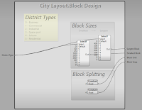
Block design constants, parameterised by district type

Whitebox

For testing purposes I added a simple cuboid as a placeholder building to each block.
Simple white-box building added to each block for test purposes
This is just a proportion of block size for now, with the height chosen randomly.  In reality a block may eventually have multiple buildings, but for now I just wanted to get a feel for how the city would look and investigate the detail levels at different distances.
View across 'white-box city'

Detail

Apparance is built around the premise of bands of detail extending out from the viewpoint, each higher detail one built based on re-synthesising the lower detail procedures.  As we start to build more detail into the city we need to begin setting up the integration with the detail management in the engine.  Since each re-synthesis is performed using sub-procedures with exactly the same input parameters, something else must provide the ability to change their behaviour as different detail results are required.
Re-synthesis of procedures for successive depths in the detail hierarchy.  How do they know what detail level to generate?
As the scene is progressively refined to give more detail, the blocks the world is divided up into get smaller.  It is this that a procedure can check to decide what level of detail to generate itself at.
For our city blocks we will switch between an extremely low detail (flat) rendition for far in the distance, to our normal block procedure as their size decreases.  This will have the effect of gradually populating the area with more buildings as we get closer.
Switching out the blocks in the distance for a simpler representation.
The normal blocks intercepted and replaced depending on our detail hierarchy block size.
The Distant Content procedure we are using will make use of a common modelling primitive; a rectangular patch with automatic detail improvement.  This also uses this detail switching to break down and subdivide its surface into smaller pieces to add detail and reveal intricacy as you view mode closely.  Here we see an example of it increasing in detail.
Successive refinements of a generic rectangular patch, introducing more detail and some variation.
Putting this all together and we get a rather satisfying reveal of detail as we move across the city.
Detail transitions and reveal testing across white-box city

Diagnostics

Setting up the detail management in a scene is quite tricky at the moment.  I am still exploring how it can best work and what can be done to improve the user experience.  To help understand what the engine and your procedures are doing a lot of diagnostics displays options are available.
Various diagnostics settings and statistics for a view-port and scene rendering.
These have been added gradually during the development of the engine and this week I've had to revisit them and add a few features to help fix problems with the detail tracking and blending system.  These features are going to be essential in debugging procedures and understanding what the engine is doing with them so it's worth having a look at them now.

Display Modes

There are several colourising modes to visualise various mesh rendering information.
Colourising of meshes to visualise state and show information spatially
The scene node hierarchy can be visualised; a progression of hues used to colour each depth level.
Visualisation of the scene node hierarchy, coloured by depth
The detail range bands and various transition boundaries can be shown to check where the blends are supposed to be happening.
Visualisation of the detail tier ranges, coloured by depth

Focusing

Most of these displays, as well as models and meshes can be selectively singled out using sliders to help close in on specific issues in the scene.  For example, information about, a particular model, in a particular node, in a particular tier of the scene hierarchy can be viewed:
Focusing in on a specific model in the hierarchy
Looking at the node diagnostics panel, we see that this model can't be refined any further because the procedures don't have any sub-procedures small enough to fit in the next scene node size down.
This model in this node can't be subdivided, so no more detail can be generated in this area.
For more information about the procedures in question and how the analysis for resynthesis worked out we can trigger a re-synthesis and analysis of a model which also allows us to see the evaluation tree (via an external GraphViz step).
Here we see the refinement capture analysis failing at our temporary content procedure.
Here it is clear that all the leaf procedures are un-refinable and need more work (which we knew as this is a test procedure of limited ability).

Debug Camera

Using the debug camera and some of these diagnostics overlays we can see the detail reveal effect 'from the outside'.  Here the details is added and revealed around the view-port after a scene reset.  As progressively more detailed versions of the scene are synthesised we can see the extent of each expanding.
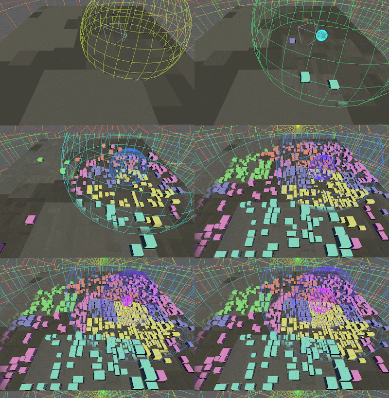
Detail regeneration and reveal after scene reset as seen from external debug camera position.

Next

These recent posts have been fairly dry and focusing on dividing up spaces rather than the more interesting process of filling them with things.  We will start seeing some more exciting things soon, I promise :)

Thursday, 23 January 2014

Procedural Closures II

I now have enough of the four elements described in the last post implemented, to try out the dynamic hierarchical detail generation described.  Here's a (rather extreme) test case in action:

Menger Sponge - extreme subdivision test case

Here you can see successive sub-procedure expansions being made as the camera approaches the model.  Apart from the complexity involved in splitting up the space into 27 parts and adding 20 sub- cubes each time, the procedures - being recursive - are fairly simple.  This test case rapidly runs out of memory; a) because the object complexity escalates by a factor 20 times with each depth level, but also because b) I don’t recycle generated blocks yet. :)
After playing with it for a while and trying to build more conventional objects this way (house/street, simple landscape), I've decided that my approach to the authoring of them leaves a lot to be desired and will have to change.  To summarise the process, it works in the following way:
  1. Build a hierarchy of procedures to describe your object, parameterised by (at least) the space it is to occupy and the detail level required, and with a secondary geometry output for capture. Each sub-procedure should be parameterised in the same way where possible. 
  2. Procedures suitable for capturing (i.e meeting some criteria) are explicitly marked as such in the editor by selecting which inputs and outputs are to be assigned each meaning required (above).
 My main gripe with this process is the amount of extra mess this introduces when building procedural models.  Secondary (and somewhat related) is the fact that it is proving very hard to explain how to author models in this way.  It is just too explicit, too manual if you like.  I need a better way, and it needs to be as automatic as possible. 
I have been hypothesising that it is possible to gather information about a procedural hierarchy as it is being synthesised and perform an analysis of the structure such that suitable capture points can then be extracted and kept for subsequent detail generation automatically.  To help better understand the problem space, i.e. what exactly does the synthesis process look like, I decided to get Apparance to spit out enough information to visualise the process.  This would then allow me to browse the evaluation tree, looking for patterns, surprises, and insight into the rules that might be used to extract what was needed.
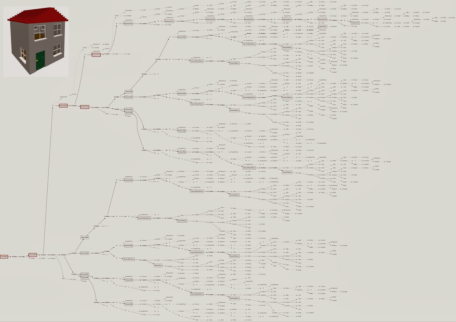
Visualising data you say. Trees you say. Well, a tweet from a friend of mine reminded me of GraphViz which I'd seen used to analyse large asset database dependency graphs in the past but not had cause to investigate myself…  a quick download, documentation read, and 'hello world' graph and I was ready to give it a go.  In a couple of evenings I'd got the evaluation tree for a test house displayed nicely.

House synthesis graph
House synthesis graph (click to enlarge)
 Salient features you can see here are: 
  • Procedures are shown as boxes, operators as plain text, each with, any sub-procedure/operator evaluations at the end of arrows heading to the right. 
  • Branches that yield geometry are solid, dotted branches are for any other types of value. 
  • Branches that lead to at least one procedure are black, those that only lead to operators are grey. 
  • You can see operators (or procedures) that appear to be missing further evaluations where those evaluations have already been performed by an earlier evaluation and are effectively cached. 
  • Procedures that contain both procedures and operators that generate geometry are the lowest point that can be captured since operators aren't designed to be captured (as they won't sub-divide).  I have (manually) marked such procedures in red.
  • It is clear that this house structure (as it stands) isn't best suited for sub-division as there are only a few suitable capture candidates high up the synthesis tree.
Initial thoughts lead me along the following lines:
  1. It should be possible to evaluate and automatically capture procedures. 
  2. Some means of hinting at 'bad' structure should be presented in the tools to guide model development. 
  3. There may be more rules to be added later.
  4. Improvements in the tools can be made to aid the construction process, for example: quick sub-procedure creation from selected elements.
Anyway, I've waffled on for quite long enough.  I shall endeavour to work on this.

Next time I'd like to talk about 'detail'; what it means and how to quantify it.

Tuesday, 18 June 2013

Procedural Closures

Previously I've been working on proving the synthesis and editing process of a single 'object' within a fixed geometry/calculation memory budget (the synthesis buffer).


Since this doesn't scale and won't let me achieve the ambition of large procedural worlds, we need something more.  This is where Phase II comes in; a system to hierarchically synthesise multiple objects of successively reducing scale and increasing detail when and where it's needed.  This is based around a kind-of 3D subdivision of the world with more subdivision and detail near the observer and less further away.  There are a number of parts to this investigation:
  • The synthesis system needs to support the concept of closures; snapshots of a procedure and its input values that can independently drive further synthesis.
  • Graphical bodies need to support sub-bodies, each capable of containing procedure closures to drive successive synthesis steps.
  • Procedures need to be able to generate higher detail closures from sub-sections of a procedural model to be used to populate these sub-bodies.
  • The renderer needs to be able to switch between low density bodies and equivalent high density sub-bodies according to distance from camera (and when they are available to draw).
This is the bare minimum needed to effectively prove the principals of phase II and enable generation of scenes much much larger than a single synthesis step can generate.
Wish me luck, I'm going in...