Showing posts with label synthesis. Show all posts

Monday, 3 October 2016

One Million Bytes

A slight aside today while I play with futuristic skyscraper shapes.  I'm not going to talk about cities, instead this post is about an interesting technical aspect of the synthesis engine; the use of the call stack.

The Stack

Typically the stack is something that most programs and programmers don't need to worry about, ever.  Programs tend to rarely have a call graph that goes even remotely near the stack depth limit.  Of course we have all hit stack-overflow situations, but these are usually due to either:
  1. A function accidentally calling itself (either directly or indirectly).
  2. A recursive algorithm not terminating properly.
Both of these are just bugs you would hit during development, fix, and move on.  Sometimes though you may be explicitly using recursion to solve a problem and need to be wary of how deep the recursion goes.  Usually in this case you would just tweak the code to stop it running out of stack space, or perhaps your data-set is of limited complexity and it just works, so you can ignore it and again just move on.  With Apparance however we have to be a bit more careful.

Tree Evaluation

The synthesis process in Apparance is implemented as an operator-tree evaluation.
Simple tree evaluation example
This means that starting at some root procedure we evaluate its output, triggering this sequence of events:
  1. The graph inside the procedure is instantiated and connected up.
  2. We find what the procedure output is wired to, and evaluate its output (recurse to step 1).
  3. At some point we reach a fundamental operator instead of a procedure.  Evaluating its output results in some code being executed to perform its intended function.  In order for it to be able to do this though it needs input data, which it requests (another function call) as required until it can return with the calculated output result.
  4. We find out what the operator input is wired up to (this happened in step 1 for its containing procedure).
    1. Usually this will be another output and we will evaluate that (step 2).
    2. If our input is actually wired to a procedure input, then in a similar way to 4 we have to see what that is wired up to and recursively follow it until we either reach another operator output (step 2 again), or we reach a constant value.
  5. On reaching a constant value we now have data to pass back up the call graph and we can return.  There are a couple of ways constant values can appear in a procedure:
    1. Embedded in a procedure itself as a constant input.
    2. As an input parameter supplied to the root procedure.
    3. Output-only operators that obtain the value from outside systems, e.g. mathematical constants like Pi, or useful synthesis state like the current block size.
The upshot of all this is that as we dig deeper into our procedure graph, and at every step towards some constant data value, we are making deeper and deeper function calls.

Data Driven Code

Normally the execution call graph is largely hard-coded into a program; conditional branching changes the exact shape of this graph, and recursion can cause chains of similar shaped sub-branches to push it deeper, but it is still largely predetermined in behaviour.  During development, the stack usage may increase, but this maximum will largely not change during the execution of the program.  As a consequence, for most programs it is impossible to blow the stack in every-day use.
For a data-driven situation however, you can no-longer make this assertion; we don't know how deep our procedures will end up going when we are building them in the editor.  It is very simple to accidentally create a procedure that recurses for-ever and instantly overflows the stack.
Simplest procedure that overflows the program stack.
This is a problem since these crashes happen at edit time, when the application is in the hands of the end user, and not during its development where a debugger and developer are at hand.

A Walk In The Dark

In some senses, every program is a ticking time-bomb.  Are you really aware of how close your program runs to the stack limit?  Do you just ignore the problem since you've never hit it?  Do you even know how much stack space is available to your program?  It's a bit like taking a night-time stroll on the cliff-tops, everything is fine, until it suddenly really isn't.
It's a bit of an odd situation because languages don't really acknowledge the existence of a stack limit and it seems a little talked about point.  There don't seem to be any ways to query the stack, or work out the current depth, using standard library calls.  This may be because there are ways to hand code this and it's such a rare use case that it's just not worth the effort supporting it, or alternatively it is acknowledging what should be entirely an implementation detail that the programmer should make no assumptions about.  Anyway, I need to know the limit and I need to monitor the depth as procedure evaluation is performed and so in the absence of any library support for this it's down to a hand-rolled approach. 

Get A Tape Measure

First, how deep are we?  A few searches online reveal what I suspected; that the simplest way to measure how deep you are in function calls is to take the address of a local variable (or function parameter) at the start of the program and compare it with the address of a local variable in your current function.  I created a macro to do this:
 #define CURRENT_STACK_LOCATION(a) ((uint64_t)(void*)&(a))
Used like this:
 int a;
 uint64_t stack_pos = CURRENT_STACK_LOCATION(a);
During synthesis this is evaluated each time we dig deeper, and compared to the initial stack position.  If we go too deep, we flag the error and abort the synthesis, unwinding the stack with returns triggered by an error check.

How High Can You Get?

The other important question is "how big is the stack?".  There doesn't appear to be a way to measure this in code and some investigation reveals that this is something you can set in your EXE project settings (for C++ project), or via some EXE fiddling (with EditBin.exe) for C#.  In both cases though, the default seems to be one megabyte.
Assuming this 1 MB is actually 1,048,576 bytes (2^20) I decided a 1,000,000 byte threshold would leave a nice safety margin after triggering an abort of the synthesis run.  This seems to work fine, and you can see the results of this with the simple test case (proposed earlier).
Results of simple stack overflow test procedure running.
We managed to get to an evaluation depth of 15,624 and it was a final stack frame of (at least) 96 bytes that pushed us over the million byte limit.  This is plenty of space for very complex procedure evaluation, but with the safety net of knowing you aren't going to crash.

Engineering

It's quite likely that I have missed some useful API call or technique that could have saved me some time or prevented various assumptions here, but I guess this is an engineer's approach to the problem; measure, try stuff, get something that works, and test it.  It seems to work, and until I find a platform/machine/OS/scenario where it doesn't (or a suggestion to improve it)  I will consider it solved for now.  If you have any suggestions, or concerns, please chip in below.

Thanks

A quick thank-you to those that came up for a chat and see me demo some of Apparance at last weeks Tuesday Night Gamedev Pub gathering in Guildford.  There were many good questions and interesting conversation, and I could see that the whole project was making people think, hard (either that or the beer was making it hard to think).  Your questions and chatter prompted the writing of this post.  I hope to demo again next time for those that missed it.

Wednesday, 28 September 2016

Future City: Update 6 - A Balancing Act

Industrial Zone

Using the previous steel structure procedures and some new bits and pieces I've been building a few elements for populating the industrial areas of the city.  For now we have:
  • Warehouse or factory building, with roof-top windows/solar panels, and chimneys.
  • Round storage silo or tank, with and without steel support structure around it.
  • Simple tower based on the steel-work structures.
  • Simple chimney of a couple of different styles.
Structures for first-pass industrial zone
During the creation of these, I've been regularly checking the look of the city.  I was pleased with the initial appearance and the variety and layout was working well giving a good view.
Structures in use throughout the industrial districts.

A Recurring Problem

As more elements and more detail were added, holes in the industrial blocks often appeared.
A hole in the industrial zone
This is an indicator of a procedure synthesis running out of buffer space, due to either too much geometry (triangles/lines) or too much calculation (procedure depth/complexity).  To find the problem procedure a bit of digging using the view diagnostics panel is required thus:
  1. Set render depth to show only the tier with the problem in.
  2. Turn on octree node display.
  3. Set octree node depth to match render depth selected above.
  4. Set the node highlight to the node surrounding the problem area.
First stage of diagnosis; what is the error?
This should show up the actual error message (stat shows first error message under node).  To see exactly what happened during the synthesis of this model we can perform these further steps:
  1. Open the engine dev panel to show the synthesis monitoring panel.
  2. Switch on node model filtering to only render models under this node.
  3. Set the model select to only render the problem model.
  4. Request synth analysis graph generation (triggers re-synth).
Second stage of diagnosis; which exact model?
This will re-synthesise the model (shown in the synth panel) so we can look at the output stats in more detail.
Third stage of diagnosis; what sort of memory did we run out of?
From this we can see that we are running out of parameter buffer (abbreviated to 'Control' here), the memory used for all the information flowing between and through the procedures as the calculations are performed.  This will be because the city block sub-division is quite demanding due to there being quite a depth to the process between the top level of the city at which we are starting and where we actually start to generate geometry.

Turning Up The Heat

Hitting these problems has left me feeling a bit in the dark about how well the system is performing in general, how close we are to having them happen again else-where, and where else we may need to improve the procedures building our scene.  It is a balancing act fitting the design and requirements into the resources available (as is often the case), but this is going to be a common workflow occurrence and we need more tools to help us monitor the situation as we work.
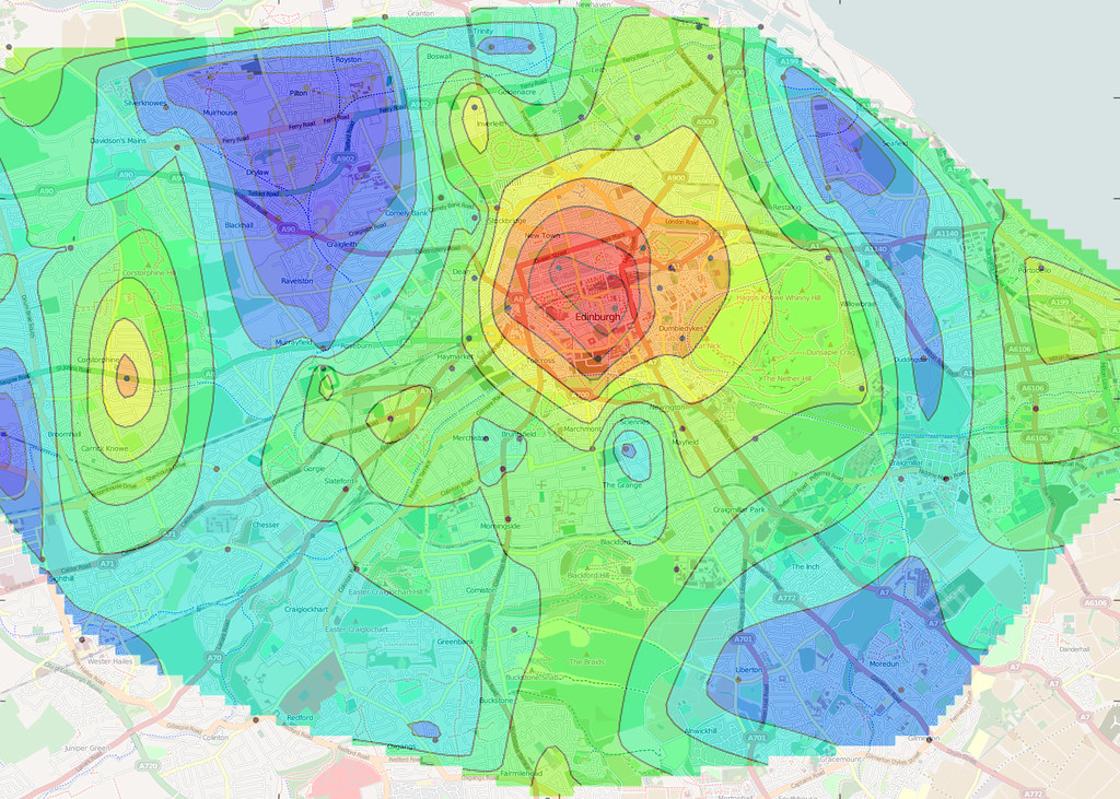
A visualisation tool often used for assessing the overall level of something and getting a good feel of how some value varies across a space is a heat-map.
An example of a heat-map
There are many metrics we could benefit from being able to visualise such as:
  • Rendering cost (triangle count, draw calls, materials)
  • Memory use (system memory, GPU memory, synthesis buffer)
  • Synthesis cost (time/cycles taken, buffer use)
  • Measures of complexity (synth depth, stack use, passes generated, analysis, refinement level)
  • Scene complexity (octree nodes, model counts, mesh counts, node status)
All of these help us assess the overall cost and effectiveness of the procedures creating our world.
Some support work was required to capture the statistics needed from the synthesis process, and propagate it through to the rendering stage (with the meshes). Plus, because the output of synthesis is often merged into single meshes, we also needed a way to render parts of meshes separately to give per-procedure colourising.
Various heat-map modes: Triangles, Cost, Time, Stack, Depth
Each new display mode has its own scale configuration setting so that the range of values being visualised in the scene can be seen in the most detail by spreading them across the full colour gradient.
Gradient scaling settings for each heat-map mode
By also having a distinct colour for a 'maxed-out' value, i.e. on or above the scale setting we can interactively measure the value on a particular element in the scene by dialling the value up and down until we are on the changeover point between being the top end of the gradient and the highlight colour.
I'm not 100% happy with the choice of colour gradient, but full spectrum gradients (which I assumed would be best) seem more suited to continuous functions and not the more random patterns we get here.  Instead I'm trying a simpler black-blue-cyan-white 'icy' gradient, with red for out-of-range values (above the chosen scale setting).

Hot In The City

Testing these display modes out on Future City as a whole shows that we are actually in a pretty good position with fairly low quantities of geometry and no hot-spots that really stand out as problematic.
Triangle counts visualised across detail levels.  Only a few hot-spots at around 7,500 triangles.
It looks like we can actually afford a fair bit more geometry and detail, but at the moment we can't afford synthesis cost (hence the holes).
Typical synth stats for chunk of the city.  Scope for a re-balance I think.
In the upper (distant) tiers most models are in 5,000 to 10,000 triangle range, and the lower tiers are at about 1,500 to 3,000 triangle range, which is pretty low for assets these days, with the overall GPU memory at about 100MB with the viewpoint in the centre of the city.  The draw-calls are moderately high at about 1,000 but this shouldn't change much as more detail is added and can be improved in other ways later on (I'm not doing a frustum cull yet for example!).
So, we need to reduce the synthesis cost.  There are a couple of ways we could go here:
  1. Reduce the complexity of some of the more complex procedures, for example we could convert our super-splitter procedure (see last weeks post [link]) into an operator.
  2. We can re-balance the way each synthesiser's buffer is allocated so there is more parameter space available (and less geometry space).
  3. We can look at one of the several planned optimisation passes on the synthesis processing and evaluation itself.
  4. Other ways?  (there are always other ways).
At the moment I think it is a bit premature to bake the Splitter proc into a procedure as we lose the ability to live edit and continue to improve it (much slower turnaround).  Some investigation of the usage of buffer memory would be helpful in deciding on a new parameter/geometry split for the buffers, perhaps with a buffer use heat-map mode?  I didn't want to get into optimising the synth system yet as I think I can get more elsewhere first and it's tricky work.

Hot-line

I did do some work simplifying the steel tower procedure, which seemed particularly bad, using line primitives (which I have so-far not needed).  In the far distance, the steel beams reduce down to 8 triangles each, but this seemed too much so I added an extra detail switch to a single line segment.  This helped the geometric/visual detail level, but didn't  help the synthesis complexity as we were still having to sub-divide down a lot to get to the individual girders.  Instead of relying on these line based beams I remembered I had a line grid primitive (originally used to draw the ground-plane grid) and so switched this in at a higher level for the steel-work side sections.  Thus each tower is now made of four grid primitives in the distance.  I took this a stage further by double the grid cell size progressively too as I noticed that the fixed width (screen space) line rendering becomes a solid block when the tower is really small.  This helps keep it looking thinned out and again reduces the render cost.
Reduction in tower complexity at lower detail levels by use of line (grid) primitive.

Late Night Ideas

One night last week I couldn't sleep for thinking about these problems and an enticing thought occurred to me about how I can neatly improve this synthesis depth/complexity problem by an order of magnitude and allow lots more detail for the distant city.  This will help a lot for aerial views of the city where you should be able to see a huge amount of small detail when at a considerable distance (probably the worst case scenario).  I think I'm going to explore this next after playing with the synthesis memory balancing.  More details next time… maybe…

Monday, 27 June 2016

An Introduction to Procedures

As there is a huge amount to cover I'm going to spread it out over multiple posts.  The first few will describe the technology (engine) and after that I'll cover the tooling (editor).  This will by no means cover all the technical detail, but it should give you a good idea of how it works and what (I hope) it will be able to do.

Authoring

Currently the engine allows building of procedural models; objects formed of triangles (and lines) and rendered in a 3D viewport.  These are expressed as 'procedures'; collections of modelling and calculation operations that feed into each other forming a network or graph.  The 'inputs' to this are various constant values within the graph and the output is a 'value' corresponding to the generated geometry.
A simple procedure and the resulting model
Each node is some form of fundamental operator (like add or subtract) implemented in code, or it can be another procedure, itself made from operators and procedures.  The term 'operator' will be used to mean either in the context of a procedures content as once placed down they can be treated in exactly the same way.
A multiplication operator feeding into a luminance procedure
Each operator generally has one or more inputs and one or more outputs, which can be connected up to other operators.  An input can only be connected to one output but an output can connect to multiple inputs.  There are several fundamental data types available for information to be passed between operators.  So far we have: Integer, Float, Bool, Colour, Vector, Matrix, String, Frame, and Model Segment.  These last two are explained more below.  Unconnected inputs are considered constants and the value can be explicitly specified.
Operator inputs of various data types
When creating a procedure, you get to define it's inputs and outputs, and their names and types, these then become available for connecting-to wherever an instance of the procedure is placed down.
Procedures represent blocks of functionality and can easily be used to encapsulate and re-use groups of operators.  For example you might build a colour blend procedure out of mathematical operators if a dedicated operator wasn't available or didn't meet your needs.
Bespoke colour blending procedure
The new blend procedure in use

Operators

There is a small library of built-in operators implemented already to build procedures from, these are roughly divided into:
  • Mathematical operations - all the usual maths functions.
  • Comparisons and conditional switching - test and flow control.
  • Conversion - e.g. changing type or break-out/re-combine (for multi-element types).
  • Constants - operator inputs are editable constants, but constant operators are useful for sharing values.
  • Modelling - create and manipulate primitives (cube, cylinder, paint, distort, etc).
  • Space defining - subdividing and specifying spaces to be used for containing objects (Frames).

Some of the operators available so far
There are hundreds more of these I need to support (something for a future post), but this is plenty for me to test and prove out the principals.  In fact this current limitation means I have to be inventive and really means I push the capabilities of the procedure system to see what I can achieve.

Modelling

Currently there are only two triangle primitives (Cube and Cylinder) and two line primitives (Line and Grid).  The only reason I haven't written more yet is that I have managed to achieve a surprising amount with just these.  All the screenshots you can see so-far are mostly built with the cube operator and an occasional cylinder.  As we will see though they do provide a fair bit of control over how each can actually be used.
Once I got to the point where the geometry synthesis was basically working and I started building shapes I found that a large part of building up objects is actually splitting up the space it is going to occupy into smaller spaces.  This happens at many depths and in many different ways.  There are parallels here to laying out elements on a page or in a user interface, so many concepts like centring, distribution, and offsetting apply equally to 3D space. To facilitate this in Apparance I found a data type to describe an oriented cuboid in space was ideal for this.  These I call 'frames' and operations on them form a large part of the object construction process.
Space partitioning operators in use (highlighted yellow)
Starting with a frame describing the location, orientation, and dimensions of the object being created, you break it down into sub-frames until you reach a point where a single primitive fits exactly, at which point you feed the frame into it generating the geometry needed there.  This aspect of modelling needs a post to its self really :)
Geometry generated by a primitive operator is passed around the graph using a 'Model Segment' data type.  This rather esoteric type is just a way of remembering where in the modelling buffers the vertex and triangle information for that primitive has been put.  A 'combine' operator is available to merge two segments of geometry together so they can be treated as one.  All modelling should result in a single Model Segment output at the top level and it is the geometry enclosed within it that will be displayed.
Part of the appeal (to me at least) of procedural generation is parameterisation.  Anything we build this way can have any aspect of its form exposed as a tweakable parameter.  This may just be the desired size of the object, it might be the thickness of the frame on window, the colour of a building's roof tiles, or the probability of a wonky brick in a wall.  In order for a given parameter to affect the modelling process its value will usually need to be massaged into some other form by using mathematical, conditional, and logic operators.

Synthesis

The process of turning procedures into models that can be rendered it called 'synthesis'.  Starting with a root procedure to be viewed in a 3D scene the synthesis engine starts by instantiating it in memory with any input values needed and requests the geometry via the appropriate output.  This triggers instantiation of all the operators within and their interconnections.  Following the 'flow' of the data connections back from the required output and digging down into procedure within procedure all the functionality needed to produce it is executed.  Requests for output values from leaf operators, ones with actual code behind them causes that code to be executed.  Procedures and operators also call upon their inputs which then cause the evaluation to elevate back up to the level above and follow the connections already in place when the containing procedure was evaluated.
Evaluation tree for the table example
Because procedures are instantiated as they are needed, it can support recursion, i.e. a procedure can include instances of itself.  As long as there are 'exit conditions' defined to limit the recursion depth this turns out to be a really useful way to build a lot of structures.  I discovered early on that this can be used to implement arrays of objects by progressively subdividing until the required object size was reached.  I thought I would need array support explicitly but so far recursion has served well in its absence.
A recursive procedure called "Recursive" that includes itself.
Output of the recursion example
To help with scalability and performance, multiple synthesis runs can be performed in parallel on several separate synthesiser instances.
Four synthesisers running in parallel, busy building geometry
Each has its own pre-allocated chunk of memory as working buffer, used in a non-freeing manner and only reset at the end of each run.  This makes allocation of parameters, values, operator state, and any intermediate data extremely fast and all values effectively immutable, simplifying the operator graph evaluation logic.
A breakdown of how memory was allocated during synthesis

Next

Quite a lot to absorb I'm sure.  I'm happy to answer any questions.  Next time I'll talk about the renderer, some of the less glamorous code supporting everything, and how the project is set up.


Tuesday, 11 June 2013

Approaching Phase 2

Oh my, yet another year.  Not big on progress news are we.  Well, I have not been idle (except where blogging is concerned), and a lot has happened.  Let's start with a screenshot:


This is the current state of my experimental procedural modelling system, called 'Apparance'.  Here you can see a number of significant improvements over my initial prototype.  I have visual editing of the procedures, fairly advanced property editing panel, and a bigger list of operators to build with.  This represents the final stage of what I have come to call 'Phase 1'.  This is where I prove the first key element of my project; that of visual editing to drive procedural modelling.  I also wanted to take it to the point that it could stand up as a 'minimal viable product' that someone could play with without any need for tricks, manual hackery and workarounds.  I am considering releasing the binaries for people to play with to get some feedback and test the water a bit.  I've collected a few more pictures from its development history over the last year in an Apparance development gallery.
No promises when, but next time I'll talk about Phase 2...