Monday, 18 July 2016

The Procedure Authoring Process

Being a visual tool where all content is created within the editor it is of paramount importance that the authoring process is a smooth one.  The tools and UI are being developed to be a low friction and intuitive experience, and I am always thinking about ways to improve them.  Let's take a look at the procedure authoring process.

Managing Procedures

The first step is to add a new procedure to the procedure browser.  Pressing Alt+N creates one called "new procedure".  It will inherit the category of the currently selected procedure.  Single click to select a procedure (highlighted in yellow) and you will see its properties appear in the property panel.  Here you can change its name from the default to something suitable.  If you want, you can change its category too.  As you rename or re-categorise a procedure it will move to the appropriate place in the procedure browser.  Scroll around or use the filter box at the top of the panel to find it.
Creating a new procedure

Procedure Files

A procedure is stored as XML data in a .proc file on disk, along-side this lives a .procedit file containing any data that is only needed in the editor such as visual graph layout and element descriptions.
Procedure files and their editor data companions
Each category has its own folder on disk.  As you rename/recategorise a procedure, these files are renamed and moved around accordingly.

Viewing & Editing

When you are working on a procedure you will probably want to see the results in the 3D view, to make a procedure the subject of this view select it and press the View button at the top of the browser panel.
To edit the procedure content, either select it and click the Edit button or just double-click on it and it will open in the procedure graph which we will look at next.
Editing and Viewing a new procedure

Procedure graph

The main part of the editing window is dedicated to viewing and editing the procedure graph.  A procedure has a perimeter surrounding it's content as well as hosting the input and output connections for it.  The procedures title appears at the top of this area, inputs on the left, and outputs on the right.
The viewing area can be panned around by holding the right mouse button and dragging, and zoomed in and out using the mouse wheel.  Normally the view is fully zoomed in and you will only need to zoom as you work on larger procedures.

Operator Instances

The most important part of creating a procedure is the adding of operator instances into it.  This is done by dragging an operator from the procedure or operator browser panel onto the procedure.
Placing operators by dragging onto procedure
New instances are unconnected and have default values for all of their inputs.  Operators can be removed by selecting them and pressing Delete.

Selection & Manipulation

Operators (and procedures) placed in your procedure can be singly or multiply selected to allow movement, and input value editing.  Shift+Click to add to the selection, and Control+Click to toggle inclusion.  You can also drag a marquee (from an empty part of the window) around operators to select them.  Click on the empty background to deselect.
Selected procedures can be dragged around to be repositioned, both individually and in multiselected groups.  If you move operators near to the edge of the procedure the boundary will be expanded to accommodate it.

Wiring

To use an operator it needs to be connected up with the visual wiring metaphor we use to show where inputs should get their values from.  Each input and output has a name label and a connection point.  Hovering over a connection point and dragging creates a wire attached to that point.  You can now interactively choose the appropriate connection point you want to connect to.  Compatible connection points (same type) are highlighted during this process.  Hover over the target connection point and release the mouse button to make the connection.
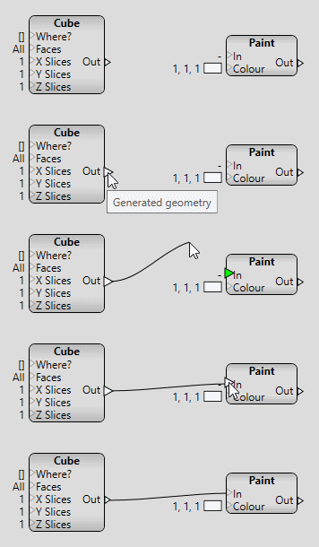
Connecting operators together
Existing wires can be moved around easily by grabbing one end and dragging it to somewhere else.  As you hover over a wire it will highlight, both the whole wire (thicker) and one of the ends (white).  This helps you see what a wire is used for in a complex procedure, as well as allowing you to specify an end to be reconnected.  If you drag a wire and drop it away from any connection points the wire will be removed.  Any disconnected inputs will revert to their previously set constant value.
Highlighting and disconnecting wires

Constants

Operator instances with unconnected inputs assume a constant value.  To specify this value simply select the operator and the property panel will list its inputs and values for editing.
Editing an operator instances input values
Connected inputs can't have their value set as they implicitly get their value from another output which is evaluated at synthesis time.

Procedure IO

Procedure inputs (along the left edge) and outputs (along the right edge) are created by starting a new wire on an operator output or input and dragging it outside the procedure boundary.
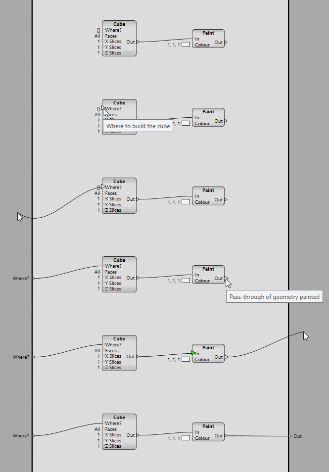
Creating procedure inputs and outputs
By default this new input/output assumes the name and type of the operator connection point you start from but they can be edited in the property panel by selecting the whole input or output area.
Editing procedure inputs
Editing procedure outputs
Procedure inputs and outputs can also be selected individually for editing, or removal (press Delete).
Once created, procedure inputs and outputs remain present and can be connected/disconnected/reconnected the same way as operator instance inputs and outputs.  In fact; procedure outputs behave exactly like operator instance inputs and procedure inputs behave exactly like operator instance outputs.

Notes

To help document procedures, visual notes can be added.  These are rectangular panels with a title and description text you can adorn a procedure with to explain what is going on.  You can also use them to surround operators to group them such that they can be moved around as a unit.  To include/exclude an operator from a group just drag it into or out of the note boundary.

3D view

The currently viewed procedure is submitted for synthesis and the resulting models displayed in the 3D renderer view-port.
The output of our procedure shown in the 3D view
As edits are made to the procedure structure and constants it is regularly re-submitted so that the models update to reflect these changes providing interactive feedback for your design.
Interactive editing of procedure data

Camera

The 3D view provides a standard range of camera controls including:
  • FPS style navigation - right mouse button to look around, WASD to move forward/strafe plus QE to raise/lower.
  • Modelling camera - Middle mouse button to pan, with Alt to orbit, with Control to raise/lower (Z axis), with Shift to move around the XY plane.  The mouse wheel can be used to adjust the orbit distance.
  • Auto-rotate - left click to toggle a carousel style orbit mode.

Grid

By default, the 3D scene includes a ground-plane grid and an axis indicator at the origin to help visualise the 3D space and scale of objects modelled.  This can be disabled and adjusted if needed by clicking the Grid tab at the top.
Drawing aids and their settings

Expanded View

The normal 3D view is fairly small but fine for a lot of modelling needs.  For cases where more detail is needed though you can toggle it to large size by pressing the Space bar.  In this view you only have the 3D view and the property panel visible.  This is a great mode to tweak values in.
Toggling expanded 3D view

Property Editing

Many elements in the editor can, when selected, have their properties displayed in the property panel for review and editing.  This used for operator input constants, procedure properties, synthesis and rendering statistics, and grid and view-port diagnostics settings.

Types 

Most data types are view-able and editable in the property panel, including; integer, floating point, boolean, colour, string, vector, and even frames have basic editing control.

Controls 

Some types have specialised controls, for example, numerical values have a slider control to aid interactive adjustment.  The minimum and maximum range of the slider is editable too, and stored with the procedure so it is there for convenient editing of the value next time the procedure is opened.
Integer inputs can also be set up in the operator definition to have enumerated values.  This can be presented as a drop-down selection or a series of buttons.  Inputs that represent a set of flags can have independant toggle buttons for each flag as well as some composite value buttons, e.g. All, for convenience.

General

A few of the more general features of the editor are worth mentioning.

Undo

Most editing operations, including property changes are command based and enable full undo/redo support.  The usual Ctrl+Z/Ctrl+Shift+Z keys are used to navigate the command history. 

Save & Load 

Procedures with unsaved changes show in bold font in the procedure browser.
Unsaved procedures appear in bold
Pressing Ctrl+S or the Save button at the top of the browser will save all unsaved work in one go.  The save process is two stage and uses temporary intermediate files to protect your data from problems during the save process.  All procedure and editing files are also kept in a back-up history.  This is stored in a backup folder alongside the procedure files.
All procedures are loaded at startup by default.  This makes managing them much simpler.

Updates

It's worth mentioning how procedure updates are propagated and applied to the models in the 3D view.  Any time you perform an editing operation on a procedure, it can potentially affect the generated output.  By following the dependency graph back from the edited procedure a list of all potentially affected procedures can be built.  This is then used to determine if the procedure you are viewing needs to be re-synthesised.
If you are adjusting a slider and potentially generating lots of edits in a short space of time the engine will try to update as fast as it can without swamping the synthesisers.

Summary

The functionality described here corresponds to the current state of play.  This is the tool set I am currently using to build and test procedures.  There is lots of scope for improvement and I have a large wish-list of features and tweaks to add.  Usually these are implemented when I am building more involved demonstration procedures and find bottlenecks in the process.

Next

I am going to be away for a couple of weeks so the next few blog updates may not be as regular as they have been so far.

Monday, 11 July 2016

A Look Around The Editor

For this post I'll show you round the different parts of the editor application's user interface.  Next time I'll dig into the editing functionality and how to use Apparance to actually build procedures.

An Editor?

Why do we need an editor?  Well, we are trying something very different here, by way of workflow, modelling paradigm, and output.  As essential parts of the Apparance concept, building a custom editing application was the only way to achieve this level of bespoke requirements.  Some of the important features it needs are:
  • Creation and management of procedures
  • Data-flow based visual graph editing
  • Preview of resulting procedure output
  • Real-time, interactive authoring and tweaking
Looking through the image gallery you can see how the user interface developed.  Initially as I was proving the procedure data representation and the synthesis process it was just driven as raw XML data.  This was fine for testing, but as you can imagine it was incredibly unwieldy for anything but very simple procedures.  As the project progressed I worked on each of the main interface elements in turn, improving them again and again.  Let's look at them in more detail.
The Apparance Editor

Browser

Good design means factoring out functionality into smaller, re-usable, chunks, and consequently we will need to be able to work with many procedures.  At the moment, procedures are organised in a simple two level hierarchy with a Category and a Name.  This will probably need expanding in the future, for larger projects, but provides a way of grouping procedures together for now.
Procedure/Operator browser and properties of selected procedure
A browsing panel lists all the procedures and as a navigation aid there is a filter box to narrow down those displayed.  As well as procedures, the fundamental operators they are built from are also listed, in their own browsing panel and can be filtered in the same way.

Procedure Editing

Once you create a procedure you need to start specifying the functionality within it and the connections in and out.  This is performed within the main area of the editor in a scrollable, zoom-able window.
Zoomed-out overview of a large procedure in the editing window
Often your operator graph will fit within the window, but for more complicated creations you will need to zoom out or pan around.  Operators are boxes with the name of the operation at the top, inputs on the left, and outputs on the right.  The procedure itself has its inputs on the left and outputs on the right too.  Consequently, the natural visual 'flow of data' is from left to right, most connections and chains of functionality propagating information to the right.  This doesn't mean you can't make connections in any direction and create all manner of spaghetti. Careful factoring out of messy bits into sub-procedures helps here.
The inputs and outputs of the procedure that you specify and name here are what you will see and be able to connect to when you place your procedure down within another procedure.
Procedure IO editing

3D View

There is a rendering window in the corner of the editor where you can view a procedures output.  At the moment all output is 3D model geometry, and as we are targeting 3D worlds this is all you need to see a model in place.
The 3D preview window
By electing to view a procedure, you are specifying the starting point of the geometry synthesis process.  In order to do this with procedures that have inputs, you need to be able to specify their values.  This can be done where you edit the input connections to your procedure (see above) and are effectively the default values your procedure comes with.  This means you can preview any procedure as each come with some starting values.  These are also the values your procedure starts with at its inputs when you place it down.
The 3D view-port has pretty standard camera navigation controls, with orbit, and FPS style movement as well as an auto-rotate mode for showing off a model.
To help with construction and spatial orientation, a ground-plane grid is drawn for you.  This is implemented as another procedure that can be edited just like any other if it needs customising (e.g. turn off, adjust colour/intensity, spacing, scale, etc).
To get a better look at your scene you can expand the 3D view to occupy the whole editing and browser area.  This leaves the property editing panel (which expands to occupy the space where the 3D view was).  This mode is ideal for tweaking values, simply select the operators who's inputs you want to change and switch to expanded mode.
Toggling the large 3D preview window

Property Panel

Most editing environments include some form of properly panel where a list of the individual adjustable elements of an object are shown.  The Apparance editor uses this for editing (and viewing) a number of things, such as: Operator input constant values, procedure IO name and description, new procedure name and description, renderer settings and statistics, view-port visualisation modes (see below) and diagnostics, and grid settings.
Property viewing and editing panel
Most data types are fully editable, some with specific enhancements such as sliders for floating point values and toggle buttons for enumerations.  Sliders have editable min/max values too so you can set them to a sensible range for the value the slider controls.

Development

In line with the live/interactive editing model adopted here, most of the user interface can be updated at run-time.  This has made development of the UI much, much faster and allowed much in the way of polish that would have otherwise been left.  The editor UI is implemented in WPF which supports dynamic loading/parsing of the backing XAML design data.  Custom text editing panels can be expanded to allow live editing of most of the editor interface.
Live editing of the editor UI
The synthesis process can be monitored in a custom panel showing each of the synthesisers, with a timeline of the jobs each works on.  For each job a breakdown of memory use and any issues encountered is displayed.  This is needed to diagnose any technical modelling problems.
Synthesis statistics and diagnostics
Another panel allows exploring of the internal engine structure and any properties exposed by each part.
Engine exploration; here showing view-port modes and settings
There are a few ways to analyse the operation of the engine, the synthesiser, the procedures, and the tools, including: GraphViz dumps of each synthesis run, the scenehierarchy, and procedure capture analysis process, as well as in-editor visualisations of the detail refinement hierarchy, the editor tool stack, and the UI stack.  All helpful in working out why things aren't going as expected and important to understand how best to build procedures that work well with the engine.

Next


Next time I will talk about procedure creation, editing, and viewing.

Sunday, 3 July 2016

The Rendering System

Previously we covered how geometry is created.  This time we will look at how it is managed and rendered.

Models

It was mentioned in my last post that geometry is built into fixed size buffers.  This limits the amount of geometry that can be created by one a procedure.  For a small object, or one of low detail (farther away), this may not be a problem, but if we are to build huge, detailed worlds then it most certainly is.  To overcome this, a number of systems and techniques are used.

Refinement

Models are managed within a spacial octree, each node being responsible for any models that fit reasonably within its own bounds.  Smaller models are managed by the small nodes deeper in the octree.
During the synthesis process, the sub-procedures used (and any bounding information that can be obtained from them) are analysed, and in certain cases stored.  The aim here is to capture a set of sub procedures that fully represent the model built, but as smaller component parts.  These parts can then be used to build more detailed versions of parts of the whole model, and which can be managed by the smaller octree nodes that are more suitably sized.  This effectively provides a way of re-synthesising successively smaller parts of any model as we need the extra detail deeper in the octree.  This 'refinement' process is driven by proximity to the viewpoint, using the deeper more detailed model parts in areas that are nearer the camera.
Successive octree levels, and the geometry managed by each

Authoring

Procedures do need to be built with this process in mind somewhat.  There are certainly ways to help or hinder the process and prevent the system from operating at its best, but the tools provide feedback and diagnostics to help you optimise them.  This is another area that I will dig into in more detail in another post.

Rendering

The rendering engine for Apparance has always been fairly basic as most of the work has been in proving out the procedure synthesis and detail refinement techniques.  All that the renderer needed to be able to do was render some coloured triangles with a couple of fixed light sources.  This was implemented in DirectX 9 and based on a fairly simple cube rendering sample.  Even with no materials, no texturing, and simple primitives I have been able to make quite a wide range of examples.
Small sample of results achieved with basic renderer
The renderer itself has been written to be fairly robust and flexible, with support for multiple viewports, cameras, and scenes, it runs on its own thread, and supports window resizing and device loss properly.

Shaders

Current focus
Driven mainly by the need to start blending between meshes of different detail levels, I decided that I needed to add shader support and this is my current focus.
With the flexibility and power shader based rendering brings I will be able to implement an elegant blending system, as well as better lighting, and start experimenting with more realistic surface properties.
I decided that I should certainly allow run-time authoring of shaders as this is an important premise of the Apparance tool philosophy.  To do this I also decided that the shader code should be procedurally constructed by the same systems the models are built.  Not only does this mean I can easily re-use shader functions and constructs, but pieces of code, and even allowing parameterisation of the shader code itself.  This should have all sorts of interesting effect creation potential.

Trouble

During the testing of DirectX 9 shaders I hit some nasty snags to do with background compilation of shaders during rendering, shader lifetime management, and finally with a crash on ending and releasing of shader resources that I couldn't resolve.  Even using my simple training app I couldn't solve the issue and under Windows 10 it turns out that debugging and diagnostics in DirectX 9 isn't supported, so no help there.  My solution was to bite the bullet and upgrade the engine to DirectX 11, which represents a significant improvement in features and support, as well as being fully integrated into the OS and with significant debugging support.  Unfortunately this did mean learning about all the differences and writing another learning app, but it seems like it will be a good move in the long run as I was probably going to need it at some point anyway and DirectX 11 has some nice improvements in the way you handle shaders that it will be good to get used to.
New rendering and shader test app for DirectX 11

Graphics Fu

Eventually I am going to need some fairly fancy rendering features to show off the models properly, such as multi-texturing, advanced light sources, high quality shadows, ambient occlusion, and maybe even global illumination.  I am treating these as 'solved' problems and prioritising many other, more unique, features over them.  I am also likely to need help with the harder graphics tech and should start to involve others in the project more closely, but that will depend on how much interest I can raise in the project and whether I can find funds to build a team around it in the future. We shall see...

Next

I was going to describe my development setup a little here, but I think I'll leave it until a later post.  Next time I'll talk about the editor and how it is used to develop procedures.

Monday, 27 June 2016

An Introduction to Procedures

As there is a huge amount to cover I'm going to spread it out over multiple posts.  The first few will describe the technology (engine) and after that I'll cover the tooling (editor).  This will by no means cover all the technical detail, but it should give you a good idea of how it works and what (I hope) it will be able to do.

Authoring

Currently the engine allows building of procedural models; objects formed of triangles (and lines) and rendered in a 3D viewport.  These are expressed as 'procedures'; collections of modelling and calculation operations that feed into each other forming a network or graph.  The 'inputs' to this are various constant values within the graph and the output is a 'value' corresponding to the generated geometry.
A simple procedure and the resulting model
Each node is some form of fundamental operator (like add or subtract) implemented in code, or it can be another procedure, itself made from operators and procedures.  The term 'operator' will be used to mean either in the context of a procedures content as once placed down they can be treated in exactly the same way.
A multiplication operator feeding into a luminance procedure
Each operator generally has one or more inputs and one or more outputs, which can be connected up to other operators.  An input can only be connected to one output but an output can connect to multiple inputs.  There are several fundamental data types available for information to be passed between operators.  So far we have: Integer, Float, Bool, Colour, Vector, Matrix, String, Frame, and Model Segment.  These last two are explained more below.  Unconnected inputs are considered constants and the value can be explicitly specified.
Operator inputs of various data types
When creating a procedure, you get to define it's inputs and outputs, and their names and types, these then become available for connecting-to wherever an instance of the procedure is placed down.
Procedures represent blocks of functionality and can easily be used to encapsulate and re-use groups of operators.  For example you might build a colour blend procedure out of mathematical operators if a dedicated operator wasn't available or didn't meet your needs.
Bespoke colour blending procedure
The new blend procedure in use

Operators

There is a small library of built-in operators implemented already to build procedures from, these are roughly divided into:
  • Mathematical operations - all the usual maths functions.
  • Comparisons and conditional switching - test and flow control.
  • Conversion - e.g. changing type or break-out/re-combine (for multi-element types).
  • Constants - operator inputs are editable constants, but constant operators are useful for sharing values.
  • Modelling - create and manipulate primitives (cube, cylinder, paint, distort, etc).
  • Space defining - subdividing and specifying spaces to be used for containing objects (Frames).

Some of the operators available so far
There are hundreds more of these I need to support (something for a future post), but this is plenty for me to test and prove out the principals.  In fact this current limitation means I have to be inventive and really means I push the capabilities of the procedure system to see what I can achieve.

Modelling

Currently there are only two triangle primitives (Cube and Cylinder) and two line primitives (Line and Grid).  The only reason I haven't written more yet is that I have managed to achieve a surprising amount with just these.  All the screenshots you can see so-far are mostly built with the cube operator and an occasional cylinder.  As we will see though they do provide a fair bit of control over how each can actually be used.
Once I got to the point where the geometry synthesis was basically working and I started building shapes I found that a large part of building up objects is actually splitting up the space it is going to occupy into smaller spaces.  This happens at many depths and in many different ways.  There are parallels here to laying out elements on a page or in a user interface, so many concepts like centring, distribution, and offsetting apply equally to 3D space. To facilitate this in Apparance I found a data type to describe an oriented cuboid in space was ideal for this.  These I call 'frames' and operations on them form a large part of the object construction process.

Space partitioning operators in use (highlighted yellow)
Starting with a frame describing the location, orientation, and dimensions of the object being created, you break it down into sub-frames until you reach a point where a single primitive fits exactly, at which point you feed the frame into it generating the geometry needed there.  This aspect of modelling needs a post to its self really :)
Geometry generated by a primitive operator is passed around the graph using a 'Model Segment' data type.  This rather esoteric type is just a way of remembering where in the modelling buffers the vertex and triangle information for that primitive has been put.  A 'combine' operator is available to merge two segments of geometry together so they can be treated as one.  All modelling should result in a single Model Segment output at the top level and it is the geometry enclosed within it that will be displayed.
Part of the appeal (to me at least) of procedural generation is parameterisation.  Anything we build this way can have any aspect of its form exposed as a tweakable parameter.  This may just be the desired size of the object, it might be the thickness of the frame on window, the colour of a building's roof tiles, or the probability of a wonky brick in a wall.  In order for a given parameter to affect the modelling process its value will usually need to be massaged into some other form by using mathematical, conditional, and logic operators.

Synthesis

The process of turning procedures into models that can be rendered it called 'synthesis'.  Starting with a root procedure to be viewed in a 3D scene the synthesis engine starts by instantiating it in memory with any input values needed and requests the geometry via the appropriate output.  This triggers instantiation of all the operators within and their interconnections.  Following the 'flow' of the data connections back from the required output and digging down into procedure within procedure all the functionality needed to produce it is executed.  Requests for output values from leaf operators, ones with actual code behind them causes that code to be executed.  Procedures and operators also call upon their inputs which then cause the evaluation to elevate back up to the level above and follow the connections already in place when the containing procedure was evaluated.
Evaluation tree for the table example
Because procedures are instantiated as they are needed, it can support recursion, i.e. a procedure can include instances of itself.  As long as there are 'exit conditions' defined to limit the recursion depth this turns out to be a really useful way to build a lot of structures.  I discovered early on that this can be used to implement arrays of objects by progressively subdividing until the required object size was reached.  I thought I would need array support explicitly but so far recursion has served well in its absence.
A recursive procedure called "Recursive" that includes itself.
Output of the recursion example
To help with scalability and performance, multiple synthesis runs can be performed in parallel on several separate synthesiser instances.
Four synthesisers running in parallel, busy building geometry
Each has its own pre-allocated chunk of memory as working buffer, used in a non-freeing manner and only reset at the end of each run.  This makes allocation of parameters, values, operator state, and any intermediate data extremely fast and all values effectively immutable, simplifying the operator graph evaluation logic.
A breakdown of how memory was allocated during synthesis

Next

Quite a lot to absorb I'm sure.  I'm happy to answer any questions.  Next time I'll talk about the renderer, some of the less glamorous code supporting everything, and how the project is set up.


Monday, 20 June 2016

What is project "Apparance"?

Videogames

I have been making videogames for over twenty years, and the process always seems to go something like this:
  1. Design game
  2. Create assets
  3. Write code
  4. Test game
  5. Repeat above in various combinations until done (ship or bust)
These steps are quite separate, mostly performed by different people (or groups of people), and the bigger the game the more of all this you need.

Some time ago I came to the conclusion that above a certain project size this model isn't very efficient for a variety of reasons. Firstly, because assets need to be worked on by multiple people, the friction associated with moving them around (conversion, source control, management, communication, builds, deployment, and loading) can mean lots of additional effort and add up to long and frustrating iteration times.  Secondly, as projects have become more ambitious, with larger scopes and game-play areas where the work involved in creating them increases exponentially (with area/volume), the cost also ramps up this way because the work a team puts in can only, at best, grow linearly with size.  In addition to this, a natural consequence of growing teams is the need for increasing communication, management, and support.  All of these pressures usually mean compromises being made to the game's detail, richness, variety, polish, quality, or seemingly low priority support work is neglected, in order to get it to fit within the budget.

Pondering this problem for several years I have formed a vision of how I think we can improve this construction and authoring process, and what the technology and tools it requires would look like.  I'm fed up with conventional approaches, the waste, the sluggish pace, the repetition, the tighter squeeze on the more fuzzy aspects of creativity like experimentation, play, fun, emergence, and instinct. I want to try working a different way, using novel and interesting techniques, powerful technology and tools, to empower smaller teams to create bigger things.  I believe we can do better, and whilst it won't be everyone's cup of tea, it's something I believe passionately in.
"I'm fed up with conventional approaches, the waste, the sluggish pace, the repetition, the tighter squeeze on the more fuzzy aspects of creativity like experimentation, play, fun, emergence, and instinct."
I've been working on this project in my spare time for around five years, with the original concept rolling around my brain for about five years before that.  As I described in my previous post I am now in the fortunate position to be able to invest all my time in this project.  So, what exactly is it I am proposing?

Vision

I want to enable rapid creation of rich and varied worlds through fully dynamic procedural generation.  I want to encourage play and exploration through fully interactive live editing of content and behaviours.  I want to make games in creative and exciting ways:
  • Rich worlds full of the variety that parameterisation and procedural techniques can enable.
  • Vast structures with intricate detail from highly scalable dynamic modelling.
  • Endless continuous worlds with no loading and no transitions required.
  • Don't repeat to save time, every instance can be unique in design and appearance.
  • Instant feedback and fast iteration from rapid and responsive tools.
  • The play and exploration that real-time control systems with live editing allows.
  • Freedom from bulk assets and offline asset pipelines by going fully run-time procedural.
  • Increasing the efficiency of creating content through asset modularity and easy reuse.
  • Making extensive use of visual editing paradigms (data-flow, node-graph).
  • Removing hard coded content, everything data driven.
  • Small footprint applications yet with all the richness of today's larger titles.
There is nothing out there that does all this, the technology just don't exist. I see this project as an adventure where we are specialising in procedural generation and real-time interactive experiences that can be applied to a variety of applications; especially games, education, and interactive visualisations. If we aspire to travel to new lands but the vehicles to do so do not exist, we must first build them.
"If we aspire to travel to new lands but the vehicles to do so do not exist, we must first build them."

What it is

This is an authoring environment in which to create your worlds, populate them, and bring them to life. The real-time synthesis engine uses procedural definitions, their input parameters, and the surrounding environment to dynamically fill out the world in more and more detail as you explore.

Apparance Editor - Procedure graph for roof section of an old house

The editor provides authoring and testing of the world through a visual flow based editing model (nodes and wires) to create the procedure definitions describing the geometry, texturing, effects, physics, behaviour, logic, and much, much more.

A standalone player application provides a non-editable view of world, for test, play, and release.
The underlying engine contains the technology driving both editor and game, using highly concurrent operation, with dynamic detail management, largely stateless data-flow control and AI systems, and all with live editing/monitoring during authoring and play.

What it is not

It is not a silver bullet and won't solve everyone's problems; Some games won't fit the development model and technology being created here.  It may be that a game relies heavily on areas that are a particular weakness for this technology. Some games are based on very tightly controlled and designed environments and behaviours. But I believe that working toward its strengths and away from its weaknesses is no different to any existing games development, more so historically as hardware and software capabilities have applied their own unique constraints on possibility.

I don't see it as a plugin for other engines; using a lot of unique techniques to achieve its aims means it may not work well in more conventional engine scene graphs and rendering.  The lack of scalability in many existing systems can cause problems too as non-scaling systems 'crowd-out' the scalable ones as a project grows.  This is a disruptive technology, and relies a lot on the interaction between the various novel techniques at play.

It is not finished yet.  This is a project that I've been working on in my spare time, and whilst showing great promise already, there is still a lot to do to.  I see many stages to its development and I will be building demonstrations and even games to show-case it at various points in the future.

Direction

This is an ongoing project and I want to involve people as it develops.  Through blogging and sharing the results of my work I hope to involve like-minded and creative people to help shape the tech and tools into something that many developers could benefit from.  I am working towards releasing versions of the tools for you all to play with to see what we can create together.  If you are interested in these ideas and the prospect of trying something different please get in touch via email, via my Twitter feed, or just follow progress here on my blog.

The Name

Logo design idea - featuring one of the first models built with the system.

Apparance (or often Apparence) refers to the outward manifestation of a person or thing, the act of being visible, what others see, the process of creating this external impression. The original inspiration for this comes from "Against A Dark Background" by Iain M Banks; The Solipsists don't subscribe to the concept of the individual with no use of the word 'me', referring to, and in a way justifying, the existence of other members of their group as 'apparences'.

Next

Next time I will bring you a full project status report, showing the current state of play and what I'm working towards at the moment.  It should be a very visual post as there is lots to see.

Sunday, 12 June 2016

New Beginnings

Tragedy

Nearly three months ago now, everyone at Lionhead was called into a company meeting at short notice to be told that Fable Legends was probably going to be shut down and the studio along with it.  Roll forward to the end of April and the axe finally fell leaving over a hundred developers, a four year project, a smaller side project, and a 20 year old studio, gone.  I don't expect we will ever know the true logic applied by Microsoft to drive this decision, and I'm sure many will speculate on this for a long time. However, due to both the huge amount of talent among the staff and a great rally of  support from the industry I am please to say most (if not all) of my displaced colleagues have found new roles, pursuits, challenges, and adventures to move on to.
The last Lionhead team photo

Opportunity

In a way I have a little difficulty coming to terms with, such tragedy has led to the opening up of a significant opportunity for me.  It has become an enabler, in the form of both a financial safety net and huge prod, to do something new.  I had been at Lionhead for over eleven years and seen a lot of change, but I was still happy there building tools and technology to support the team in making the fantastic Fable visions come to life.  I have mused about quitting to develop my personal projects before, but either the numbers didn't stack up, or the time wasn't good, or I was enjoying work.  This however presents an unavoidable boot up the backside to give it a go... and that is what I am doing.

Cogitation

This infrequently updated (and lesser read) blog that you are reading now has been my attempt to slowly document development of a spare-time project over the last five years.  It is based around a collection of ideas I've been pondering since around 2001, gradually crystallising all the different elements of what is needed to produce some exciting procedural technology that I feel should exist.  I will go into the project details in my next post, trying to finally bring together and explain all the many aspects of my vision, for now you can refer to some of my previous posts for an overview.

Introspection

During the redundancy process we all felt a bit in limbo, not really sure what was happening, or what we should be doing.  With no work to do, we were largely at a bit of a loss.  Some dusted off their CVs and job hunted, some taught themselves new things, some tinkered, some played games, some just didn't come into work.  I had some loose ends to tie up but after a while started spending more time at home on some long overdue bathroom renovation.  This served as a productive use of my time, keeping me busy, and also providing some much needed thinking space, to mull over the possibilities and directions to go.

Preparation

Redundancy included various consultation sessions and training opportunities, which I decided to give a try.  These turned out to be very useful, providing me with a good overview of self-employment, and advice on using social media and the web to drive business.  Conversations with a few friends and family members about my thoughts, concerns, and plans helped too.  Going forward I decided (at least to start with) that a self-employed, one-man-band operation would serve me best.  I have a nice office set up in our spare room (a pleasant environment with desk, chair, PC, light, supplies, etc).  Office hours have been decided (9 to 4:30, flexible).  House rules have been negotiated ('Daddy will still be working when you get home from school'). I am good to go.

Action

This weekend marks the end of my first week of my new job; working for myself, developing my project full-time.  It was always going to be a strange experience, having been an employee all my working life, but I can see myself getting used to it fairly quickly.  I like the fact that I am working on something I am truly passionate about, something that can only come from being the source of the ideas. It is weird that my spare-time project has replaced my work project and that my spare-time will need to become something else.  I will have to be careful to dedicate spare time to more varied interests as I now more than ever need to keep myself mentally balanced.

Prediction

It's a hugely exciting prospect to develop my project properly, investing the time it deserves, and giving it my full focus.  I am pretty certain that it will result in some impressive and useful results and I can't wait to share with you fruits of my labour and the process by which I achieve them.  Please join me as I embark on this adventure. I will take you through some of the business, and personal sides of it but mostly this will be a technical blog (and there is a lot of technical involved).  Exciting things are on the horizon; watch this space...