Monday, 31 October 2016

Future City: Update 9 - Apartment Construction

Apartments

I've been thinking about how to build interesting residential apartment buildings, that look more futuristic than just boxes with windows.  A few ideas come to mind:
  • Surface objects  - balconies, air-con units, ducting, etc.
  • Surface projections - bits that stick out, and in-turn have windows/etc.
  • Multi-part buildings - intersecting parts in a cluster, at different heights.
  • Non-right-angle intersections - should be do-able.
  • Buildings on buildings - large rooftops can recursively have smaller/similar buildings on top.
  • Styling - design seed can keep same style among a cluster but different between
We'll see how far this gets us.

Building Units

I started on the apartment buildings by properly subdividing a building block into obvious parts: windows, faces, friezes, separators, corners, parapets, roof, etc.
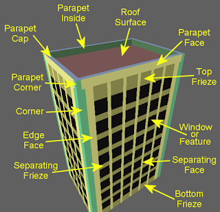
Procedure injection points on a general building structure.
This can later have a variety of proper alternatives and parts switched in and out to give them their final look.  I wanted the buildings to support intersection, so I added 'opening' parameters on each side, spending some time getting the various combinations of opening needed working.
Rig to test support for openings in the sides of buildings. 'Unit testing for procedures' in a way.
Two main ways to intersect building faces occurred to me:
  1. Clipping - Intersect, working out where the join is and just filling each part with the usual facade (window grid, etc), making some changes to the edges to fit better.
  2. Culling - Intersect, but this time just cull any windows that would become split where the join should bee (replacing them with basic wall).

Clipping has the limitation that you need to intersect at quantised positions otherwise the windows beside and above the intersecting building won't line up, but Culling means you will get areas with no windows.
I thought I'd try clipping first, and with some calculation I was able to get the intersection working.
The clipping approach in action.  Windows scale to fit space.
To support arbitrary angle intersections though the quantising requirement is going to be really hard to meet, so I also implemented the culling approach for comparison.
The culling approach in action.  Windows are removed when not enough space.
Seeing these in operation show's up the main pro's and con's.
The main differences between the clipping and culling approaches to building intersection.
On balance I think the culling approach will be less messy, especially with proper surface materials and objects.

Proper Facade

Switching the placeholder geometry for more interesting design produced some promising results:
Basic design variation examples

Next

 Now I need to look at arranging these together in interesting ways for use in the city:
  • Generating building clusters to fill the city blocks.
  • Populating the surfaces with proper features.
  • Adding some LOD support for full city use.

Monday, 24 October 2016

Future City: Update 8 - A Mixed Bag

I haven't managed to write anything this last week (or two) due to other things going on in my life (shock!), and not really feeling like I've been focused on one particular thing.  Instead of a themed post let's just have a look through what's been going on.

Refinement Fixes

Spent some time tidying up the city a bit.  There are a few places where detail refinement was being blocked so I investigated those.
  • Empty Stacker recursion procedure leaf nodes were not ignored.
Stacker Merge appears as leaf when no further content needed, but should be ignored as not a geometry producer itself.
(excuse low-res image, Cairo scaled it down because the GraphViz output was too large)
  • Temporary general triangle fill added for rooftops didn't support refinement.
Roof triangle refinement - before and after
  • Bolts had bounds that were too large, needed to be pre-shrunk.
Bolt bounds blocking refinement - additional re-size in procedure to fix
  • Mesh primitive operators were not being counted as geometry producing (which broke the fix for the Stacker recursion issue above).
Post load checks to classify operators by whether they modify/produce geometry or not.
  • Unnecessary deep refinement of surfaces meant a deluge of synthesis when you strayed very close to a surface. This was slowing things down a little so I added a limit check in the sub-division process.
Adding a refinement limit test, whilst also abstracting out the recursion check to make it more re-usable.
To help track down some of these I added a bit more error diagnostics information:
  • Capture errors show in view panel for selected node
  • Error filter slider for when too many to display at once
  • Any bounds information in the error messages is visualised in red
Additional error diagnostics - better messages, error select, and bounds rendering

More Girders

Couldn't resist more girder improvements as this has become a bit of an 'extreme detail' test case.
  • Washers under nuts
  • Proper facets on bolts
  • Threads on the bolts (hacky, but fine for now)
Washers, faceted nuts, and threads.
  • Added cross bracing to girders
  • Fillet pieces for cross bracing
Cross-bracing and attachment fillets
  • Added rolling fillets to I-beam section
  • Added welds to fillets and fixing plates
Welds and I-beam section forming fillets
All a bit excessive, but some good tests of the detail management refinement systems.  Several issues and bugs were surfaced from this work.

The Wilderness

To make the city more interesting, and provide more of a 'setting' for it I decided to surround it with a Rural district type.  Currently just green/grass, this breaks up the city tone and gives it a rounder appearance.
Rural district type now surrounds the city.
This will provide something to have as the backdrop, or vista, when height support is added and we can have hills and mountains in the background.
This was implemented by re-purposing the commercial district type and giving it a negative gradient along it's radius instead of a positive one like the central districts.  I also parameterised the location, sizes and weights of the district types so we get much greater city layout variance as we vary the city seed values.
Some parameterised city examples

Demo Planning

I'm aiming to have my first-pass city demo-able by the end of the year, and so far I feel like I'm on track for that.  I thought I'd better make a clearer plan though so I spent a morning breaking down the things I have left to do and thinking about the timings.  Here's the to-do list:
  • Finish filling out the placeholder zones (1) - I really need to fill in the residential and leisure areas as they will lend a 'more human' aspect to the city (business and industrial so far).  I'm postponing commercial and spaceport as there are more important things to focus on.
  • Implement first-pass landscape support (1) - A big thing this city doesn't have yet is elevation.  It was always something I wanted to do to add richness and interest to the city.  So we need support for a height function (of some sort), blending (to interface with flat parts), and placing of blocks on landscape (giving them the appropriate elevation).
  • Height integration (1) - Once supported, the natural areas (leisure, surround, and business in-fill) and the interfaces between adjacent elevations need content to provide pleasant and realistic transitions.  This will need to take into account block boundaries, height, and importantly; access ways (or lack thereof) between blocks.
  • Detail pass (2) - Another pass is needed to add more detail to the low-level city, that you will see when 'walking around' at street-level. This includes features like doors, windows, pavement, as well as assets such as bins, streetlights, benches, planters, and maybe trees.
  • Navigation/viewing (1) - To demo this city properly I need people to be able to control the camera in the standalone player.  This would start with basic is keyboard/mouse (FPS) support, with controller support coming later, and then maybe an attract-mode camera mode if there is time.  This would be quite involved as it will need to 'explore' the city to find good camera positions and paths (for some definition of 'good').
  • Lighting (4) - I'd really like to try out my lighting ideas, they should really bring the city alive.  This would also include some fogging/haze/sky work, and maybe some simple clouds for fun.
  • Bonus: Transparency and reflection - If I get time or want a break for something more adventurous I'll try and get some transparency and reflection support in to allow water and glass effects to be added.
Timings (in brackets) are estimated weeks.  We'll see how it goes as I am already a little behind and am still due to have some time off.

Next

I need to get the residential parts populated as soon as I can, so I'll be looking at more 'house-like' buildings and how to create them.

Wednesday, 12 October 2016

Future City: Update 7 - Building a Better Skyscraper

Sorry for the late post, a few mad things going on at the moment.  One of which was the Rocketjump event in Bournemouth which @dannyt of @Moov2 invited me to, to showcase Apparance.  A lovely little event with some great speakers and games to see, where I got to show Apparance to a few more people.

Skyscrapers

Last week I decided that the stand-in skyscrapers were too dull and not nearly futuristic enough.
Temporary, non-futuristic, skyscrapers.
I was looking for things like these:
The sort of futuristic skyscrapers I was after
(Sources: source 1, source 2, source 3, source 4)

Spaceships

I knew I wanted interesting angular surfaces and chamfering so as a starting point I imported some old hull surface triangulation procedures I made for my spaceship construction experiments.
Ship hull built by connecting triangulated pieces.
The premise behind these is that we can build up large and interesting building hulls out of simpler parts that connect rectangular and angled edges together.  However we also want to make sure we can use shapes that map well to the frame construct used to model within.  Rectangular sections are easy, and right-angled triangles aren't too much of a stretch either.  In most of the cases I wanted these were sufficient to build interesting shapes.
Hull triangulation procedures

Cross Section

To limit the complexity of the models built I decided a cross-sectional form where each side can be in-set and corners chamfered independently would still provide sufficient flexibility to give interesting models.
Example of a skyscraper cross-section (two matching chamfered corners and an inset side)
This information is passed around encoded in Vector3's (like the connectivity information), one for each side, defined as follows:
Side inset/chamfer encoding for skyscraper cross-sections.
This will be used to describe the outline of the building at various elevations, with hull triangulation providing us with frames to build the surface geometry to fit.  The cross section will be mutated at random along the way to make the shape change and evolve as the evaluation proceeds skywards.  The changes we can make are:
  1. Leave it the same - a straight vertical sided section
  2. Chamfer any un-chamfered corners - introduce triangular sections.
  3. Inset un-chamfered sides - introduce slopes and overhangs.
  4. Remove any chamfered corners - return to square corners.
These can be applied in various combinations and quantities, some examples shown here:
Example cross-section mutations
The requirement for this building section triangulation exceeded the original hull construction primitives so I created a new one specifically for this, based on the various techniques employed before.
Diagnostics display for building section surface triangulation

Building It Up

By iteratively segmenting the skyscrapers into sections, potentially mutating the cross-section at each intersection we get all sorts of building shapes.
Example skyscraper shapes

Surface Noise

Initially I filled in the surface spaces with the general purpose smooth gradient rectangle and triangle procedures I had to hand.  These however had consistency problems at their edges.  Even though the sub-division they perform to add detail does maintain coherency internally between new triangles and rectangles, there was no way to maintain this between adjacent instances of the procedures.
Incoherent detailing, particularly noticeable on triangular sections.
A change of approach was needed to fix this; instead of choosing corner variations at random and then using midpoint noise to sub-divide, a simpler approach is turns out is to use the 3D noise distortion algorithm I was already using for landscape and wobbly building experiments.
Experiments with 3D noise mesh distortion
Adding an operator to do single samples in space for this allowed me to use the output to modulate the surface detail.  This had the advantage that the noise function was based in world space and so any two evaluations that happened to be at a coincident vertex, and hence the same position in space, would result in the same modulation effect.  This produced the effect I was after and improved the look of the buildings no-end.
Moving from a mid-point algorithm to world-space noise algorithm for surface detail sub-division.

Roof

A quick triangulation hack later and I had the geometry to cap off the buildings too.
Temporary roof tops for the skyscrapers
I will re-visit this later as it will be great to add intermediate roof pieces between building sections so we get stepped in parts and mid-level terracing.  This complicates the roof calculation though as we need to in-fill between two cross-sections, as well as potentially generating railing frames around the perimeters too.

Windows

For some extra finesse I also knocked up a 'window' filler for the rectangular sections, giving a much better sense of scale as you 'walk' around them. Oh, and I've been playing with grass for the plaza areas that break up the city space a bit.  Some level of success was obtained, more work to do on that though ;)
Simple surface window detail increases sense of scale

The City

These new buildings, with a bit more tweaking and polish give a very pleasing look to the business district and are far more in-keeping with the direction I was intending the city to go.

Business District, now with added futuristicness
Design choices can alternate up through sections
Bigger and better business buildings


Monday, 3 October 2016

One Million Bytes

A slight aside today while I play with futuristic skyscraper shapes.  I'm not going to talk about cities, instead this post is about an interesting technical aspect of the synthesis engine; the use of the call stack.

The Stack

Typically the stack is something that most programs and programmers don't need to worry about, ever.  Programs tend to rarely have a call graph that goes even remotely near the stack depth limit.  Of course we have all hit stack-overflow situations, but these are usually due to either:
  1. A function accidentally calling itself (either directly or indirectly).
  2. A recursive algorithm not terminating properly.
Both of these are just bugs you would hit during development, fix, and move on.  Sometimes though you may be explicitly using recursion to solve a problem and need to be wary of how deep the recursion goes.  Usually in this case you would just tweak the code to stop it running out of stack space, or perhaps your data-set is of limited complexity and it just works, so you can ignore it and again just move on.  With Apparance however we have to be a bit more careful.

Tree Evaluation

The synthesis process in Apparance is implemented as an operator-tree evaluation.
Simple tree evaluation example
This means that starting at some root procedure we evaluate its output, triggering this sequence of events:
  1. The graph inside the procedure is instantiated and connected up.
  2. We find what the procedure output is wired to, and evaluate its output (recurse to step 1).
  3. At some point we reach a fundamental operator instead of a procedure.  Evaluating its output results in some code being executed to perform its intended function.  In order for it to be able to do this though it needs input data, which it requests (another function call) as required until it can return with the calculated output result.
  4. We find out what the operator input is wired up to (this happened in step 1 for its containing procedure).
    1. Usually this will be another output and we will evaluate that (step 2).
    2. If our input is actually wired to a procedure input, then in a similar way to 4 we have to see what that is wired up to and recursively follow it until we either reach another operator output (step 2 again), or we reach a constant value.
  5. On reaching a constant value we now have data to pass back up the call graph and we can return.  There are a couple of ways constant values can appear in a procedure:
    1. Embedded in a procedure itself as a constant input.
    2. As an input parameter supplied to the root procedure.
    3. Output-only operators that obtain the value from outside systems, e.g. mathematical constants like Pi, or useful synthesis state like the current block size.
The upshot of all this is that as we dig deeper into our procedure graph, and at every step towards some constant data value, we are making deeper and deeper function calls.

Data Driven Code

Normally the execution call graph is largely hard-coded into a program; conditional branching changes the exact shape of this graph, and recursion can cause chains of similar shaped sub-branches to push it deeper, but it is still largely predetermined in behaviour.  During development, the stack usage may increase, but this maximum will largely not change during the execution of the program.  As a consequence, for most programs it is impossible to blow the stack in every-day use.
For a data-driven situation however, you can no-longer make this assertion; we don't know how deep our procedures will end up going when we are building them in the editor.  It is very simple to accidentally create a procedure that recurses for-ever and instantly overflows the stack.
Simplest procedure that overflows the program stack.
This is a problem since these crashes happen at edit time, when the application is in the hands of the end user, and not during its development where a debugger and developer are at hand.

A Walk In The Dark

In some senses, every program is a ticking time-bomb.  Are you really aware of how close your program runs to the stack limit?  Do you just ignore the problem since you've never hit it?  Do you even know how much stack space is available to your program?  It's a bit like taking a night-time stroll on the cliff-tops, everything is fine, until it suddenly really isn't.
It's a bit of an odd situation because languages don't really acknowledge the existence of a stack limit and it seems a little talked about point.  There don't seem to be any ways to query the stack, or work out the current depth, using standard library calls.  This may be because there are ways to hand code this and it's such a rare use case that it's just not worth the effort supporting it, or alternatively it is acknowledging what should be entirely an implementation detail that the programmer should make no assumptions about.  Anyway, I need to know the limit and I need to monitor the depth as procedure evaluation is performed and so in the absence of any library support for this it's down to a hand-rolled approach. 

Get A Tape Measure

First, how deep are we?  A few searches online reveal what I suspected; that the simplest way to measure how deep you are in function calls is to take the address of a local variable (or function parameter) at the start of the program and compare it with the address of a local variable in your current function.  I created a macro to do this:
 #define CURRENT_STACK_LOCATION(a) ((uint64_t)(void*)&(a))
Used like this:
 int a;
 uint64_t stack_pos = CURRENT_STACK_LOCATION(a);
During synthesis this is evaluated each time we dig deeper, and compared to the initial stack position.  If we go too deep, we flag the error and abort the synthesis, unwinding the stack with returns triggered by an error check.

How High Can You Get?

The other important question is "how big is the stack?".  There doesn't appear to be a way to measure this in code and some investigation reveals that this is something you can set in your EXE project settings (for C++ project), or via some EXE fiddling (with EditBin.exe) for C#.  In both cases though, the default seems to be one megabyte.
Assuming this 1 MB is actually 1,048,576 bytes (2^20) I decided a 1,000,000 byte threshold would leave a nice safety margin after triggering an abort of the synthesis run.  This seems to work fine, and you can see the results of this with the simple test case (proposed earlier).
Results of simple stack overflow test procedure running.
We managed to get to an evaluation depth of 15,624 and it was a final stack frame of (at least) 96 bytes that pushed us over the million byte limit.  This is plenty of space for very complex procedure evaluation, but with the safety net of knowing you aren't going to crash.

Engineering

It's quite likely that I have missed some useful API call or technique that could have saved me some time or prevented various assumptions here, but I guess this is an engineer's approach to the problem; measure, try stuff, get something that works, and test it.  It seems to work, and until I find a platform/machine/OS/scenario where it doesn't (or a suggestion to improve it)  I will consider it solved for now.  If you have any suggestions, or concerns, please chip in below.

Thanks

A quick thank-you to those that came up for a chat and see me demo some of Apparance at last weeks Tuesday Night Gamedev Pub gathering in Guildford.  There were many good questions and interesting conversation, and I could see that the whole project was making people think, hard (either that or the beer was making it hard to think).  Your questions and chatter prompted the writing of this post.  I hope to demo again next time for those that missed it.